Pick and Place Kuka Youbot Simulation

Overview
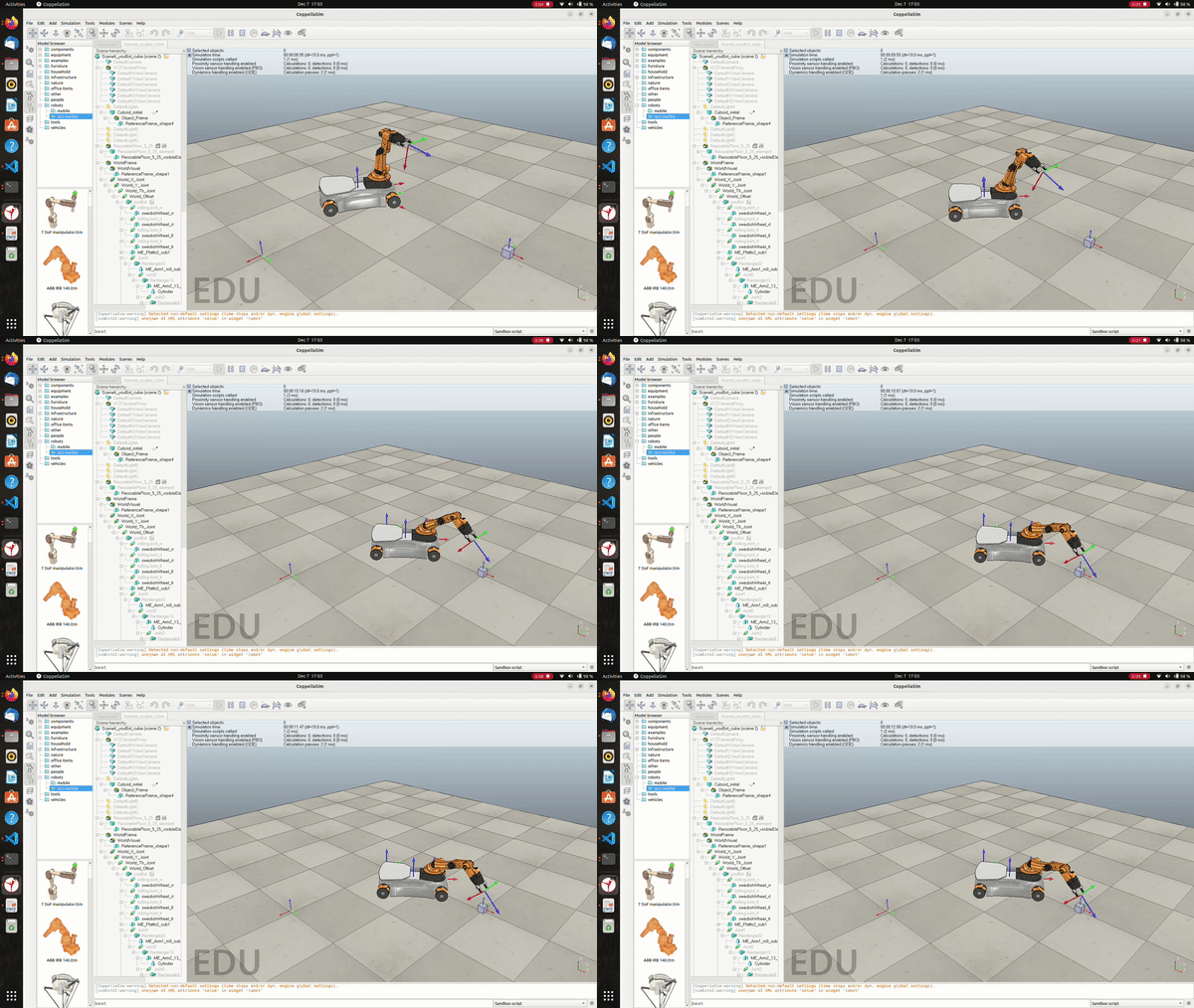
Developed a program that plans the trajectory for the end-effector of the youBot mobile manipulator (a mobile base with four mecanum wheels and a 5R robot arm), performs odometry as the chassis moves, and implements PI control to drive the youBot to pick up a block at a specified location, carry it to a desired location, and then finally places it there. This trajectory is simulated in CoppeliaSim
Trajectory Generation
Give the desired starting and ending position of the box, the trajectory of the youbot end effector can be divided into 8 segments. Evry individual segment was calculated from ScrewTrajectory from the Modern Robotics library.
- A trajectory to move the gripper from its initial to a "standoff" configuration a few cm above the block.
- A trajectory to move the gripper down to the grasp position.
- Closing of the gripper to grab the box.
- A trajectory to move the gripper back up to the "standoff" configuration.
- A trajectory to move the gripper to a "standoff" configuration above the final configuration.
- A trajectory to move the gripper to the final configuration of the object.
- Opening of the gripper to release the box
- A trajectory to move the gripper back to the "standoff" configuration.
Feedback Control
Here the kinematic task space feedforward plus feedback control was calculated. With the desired trajectory already calculated, a simple PI control was implemented. Depending on the error in the end effector configuration from its desired configuration and adjusting the kp and ki gains, the commanded twist is calculated.
Results
Best:
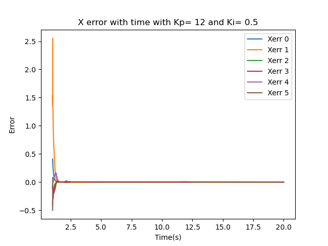
The best results were obtained using a PI feedback controller with gains Kp = 12 and Ki = 0.5. The initial configuration used is (x, y, 𝜃) = (0.2, 0, π/3). The figure below shows the convergence to the actual path where the initial error becomes essentially 0.
Overshoot:
The overshoot results were obtained using a PI feedback controller with gains Kp = 2.5 and Ki = 1.5. The initial configuration used is (x, y, 𝜃) = (0.2, 0, π/3). The figures below demonstrates overshoot deviation and then the convergence to the actual path where the initial error eventually comes to 0(approximately). In the video it can be observed that the robot has to back up after overshooting the box standoff position.
New Task:
The new task (where the position of the box was changed) results were obtained using a PI feedback controller with gains Kp = 12 and Ki = 0.5. The initial configuration used is (x, y, 𝜃) = (0.2, 0, π/3). The initial box configuration is (x, y, z, 𝜙)=(1.5, 1.0, 0.025, 0) and the goal position is (x, y, z, 𝜙)=(0, -1.5, 0.025, -π/2) . The figure below shows the convergence to the actual path where the initial error becomes essentially 0.
Know more about this project at this github link .
- © Untitled
- Design: HTML5 UP


